The pipe support framing system is designed as rigid frame bents with fixed or pinned bases in the transverse direction and as braced frames in the longitudinal direction. A pipe rack is the main artery of a process unit.
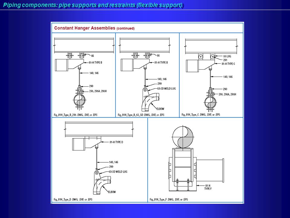
Pipe Supports And Restraints Ppt Video Online Download
Width of Pipe rack The width of the rack shall be 6m 8m or 10m for single bay and 12m 16m or 20m for double bay having 4 tiers maximum.

. IntroductionPipe-Rack Considered as Main Artery of a process plant. Design Parameter Kz Ly Lz UNL 4. Add 20 future expansion to calculated pipe rack width Pipe rack width after adding future expansion calculated width 20 future expansion 3295659 3954 4000 mm.
SlideServe has a very huge collection of Pipe rack support PowerPoint presentations. FPipe racks are necessary for arranging the process and service pipelines throughout the plant. Parisher 2001-10-24 Pipe designers and drafters provide thousands of piping drawings used in the layout of industrial and other facilities.
Generally speaking what we didnt do was take wind blowing in a parallel direction with pipe axes inside the rack so the wind and thermal load seldom added together in a long pipe rack design. Located in the central part with branches to the sides. They may also be used to support mechanical equipment vessels and valve access platforms.
However it can be increased to 8m depending on the size of the pumps to be housed below pipe rack. Pipe Rack Design Ppt 17 Download Pipe Rack Design Ppt Pipe Drafting and Design-Roy A. The layouts must comply with safety codes government standards client specifications budget and start-up date.
Or 75 of piping vertical load between expansion joints or. PIPE RACK Pipe rack is the main artery of any plant. If there is space available when making the design.
Basically Overhead piping supported on steel or concrete bents. 25 Extra space provided for future expansion. Dimensions Section Properties etc 2.
The layouts must comply with safety codes government standards client specifications budget and start-up date. Pipe racks are structures in petrochemical chemical and power plants that are designed to support pipes power cables and instrument cable trays. The horizontal load on piperack anchor bays shall be the greatest ofAnchor force from pipe stress These shall include startup and shutdown conditions.
Because it is located in the middle of the most plants the pipe rack must be erected first before it becomes obstructed by rows of equipment. This checklist can be used at design stage as well as during 3D Model Review. The layouts must comply with safety codes government standards client specifications budget and start-up date.
View Pipe rack support PowerPoint PPT presentations online in SlideServe. Interface and Assembly Final Design Review April 2003 E. Pipe Racks PipeWay Arrangement Design G.
Pipe racks are structures in petrochemical chemical and power plants that are designed to support pipes power cables and instrument cable traysThe design requirements found in the US building codes are not clear on how they have to be applied to pipe racksThis course summarizes the US design code requirements and industry practice design criteria. Minimum 3 Meters clearance provided below Units Pipe racks not crossing any roads. The spacing between pipe rack portals shall be taken as 6m in general.
Introduction Structural Arrangement Types of Pipe Rack Primary Data Required Pipe Rack Design Load calculation Example INTRODUCTION. Pipe Rack Design Ppt 111 DOC Pipe Rack Design Ppt Pipe Drafting and Design-Roy A. Pipe Rack Design Ppt 14 eBooks Pipe Rack Design Ppt Pipe Drafting and Design-Roy A.
The layouts must comply with safety codes government standards client specifications budget and start-up. Parisher 2001-10-24 Pipe designers and drafters provide thousands of piping drawings used in the layout of industrial and other facilities. We used 10 of total pipe load as a lateral thermal laod because some thermal friction went in the left.
Located in the central part with branches to the sides. All piperack longitudinal beam struts shall be designed for a compression load of 15 of the maximum adjacent column load at beam level. Parisher 2001-10-24 Pipe designers and drafters provide thousands of piping drawings used in the layout of industrial and other facilities.
Because it is located in the middle of the most plants the pipe rack must be erected first before it becomes obstructed by rows of equipment. Pipe thermal load is parallel with pipe axis. Introduction Pipe-Rack Considered as Main Artery of a process plant.
Where suitable a standard will cover more than one nominal pipe size nps so that one fit for purpose design may be used on a range of pipe sizes. Pipe racks are non-building s tructures that have similarities to structural steel buildings. PIPERACK DESIGN CONCEPTS fPIPERACK GENERAL ARRANGEMENT Length of each module shall be preferably between 30m to 42m Distance between consecutive Module preferably 6m Transverse frame 40m to 100m Piperack with single bay Transverse Vertical Bracing Arrangement Piperack more than one bay Transverse Vertical Bracing Arrangement.
Pipe Rack Design Ppt 110 Kindle File Format Pipe Rack Design Ppt Pipe Drafting and Design-Roy A. A presentation with pdf a pipe rack is the main artery of a processing unit. Written by Anup Kumar Dey in Piping Design Basics A pipe rack is the main artery of a processing unit.
Pipe rack is the main artery of any plant. To be Designed Layed out Erected first alongwith electrical cable trays. Pipe racks carry process utility piping and also include instrument and.
Pipe racks or pipe bridges are structures designed and built specifically to support multiple pipes where adequate structure is not available. Parisher 2001-10-24 Pipe designers and drafters provide thousands of piping drawings used in the layout of industrial and other facilities. PRESENTATION ON PIPE RACK Contents.
Application of all possible loads 3. This carries the pipes and cable trays raceways from one equipment to another equipment within a process unit called ISBL piperack. Schematic of Beampipe Support Structure and Pixel Package in ID.
Calculated pipe rack width 650585410325260475590 3295 mm Step 5. Types of Loads for Pipe rack Design Calculation Basic Load Cases used in Pipe Rack design are as follows LOAD 1 Dead Load DL LOAD 2 Pipe Empty Load EE LOAD 3 Pipe Operating Load EO LOAD 4 Pipe Anchor Logitudinal Load X dir ALX LOAD 5 Pipe Anchor Transversal Load Z dir ALZ LOAD 6 Pipe Surge Load X dir SLX. Some of these points are covered in following pipe rack design checklist.
Basically Overhead piping supported on steel or concrete bents. RACK WIDTH SELECTION CRITERIA 5. FSteps for Design 1.
It connects all equipment with lines that cannot run through adjacent areas. It connects all equipment with lines that cannot run through adjacent areas. Pipe Racks PipeWay Arrangement Design G.
Industrial Piping System Pipe Rack Module Fabrication Construction
Steel Frame Pipe Rack Tutorials Computers And Structures Inc Technical Knowledge Base

Test Tube Rack Powerpoint Icons Powerpoint Icon Powerpoint Templates Powerpoint

Steel Frame Pipe Rack Tutorials Computers And Structures Inc Technical Knowledge Base

Kothai Portfolio Ppt

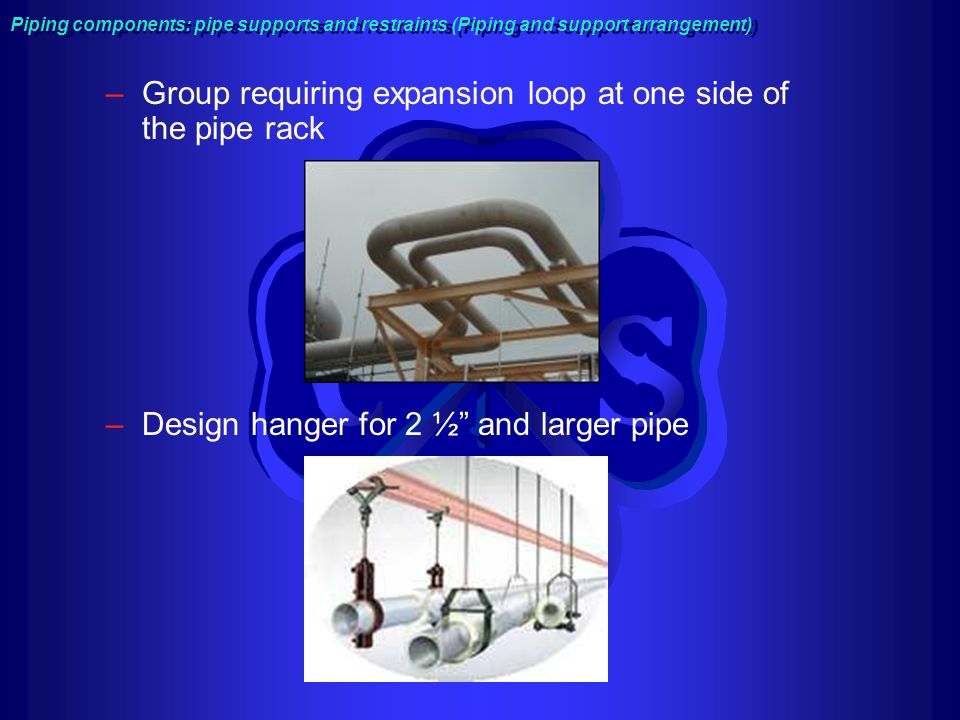
Pipe Supports And Restraints Ppt Video Online Download
Pipe Supports And Restraints Ppt Video Online Download

Kothai Portfolio Ppt
0 comments
Post a Comment